scanning MIC
Tracking yellow dots is done by scanning and properly setting the scanning parameters. The key
parameters in this process are DPI and compression.
DPI
DPI scanning represents the most important scanning parameter. The ideal state is the highest
possible DPI because the larger the resolution, the more detail of the yellow dots can be
captured in the image.

Comparison of 1200, 600 and 300 DP scans. (filter)
Image contains scans of yellow dots under different DPI profiles. In order to
make the dots visible, the green and blue channels of the RGB color model are switched on the
image, making the dots appear as purple. Illustrations that are modified by this change are
labeled with the designation "(filter)" in the description.
Compression
Compression can reduce the overall quality of the resulting image and thus blur the dots.
The best option is to use a lossless format, such as PNG.

Comparison of LOW and HIGH compression setting. (filter)
Some scanners do not have this option, so it is advisable to set the lowest possible
compression value.
frequency of MIC occurrence
To get an overview of the occurrence of MIC, 130 different random prints were collected, which
were:
- color prints
- printed in larger quantities
- containing public information or information issued by institutions (e.g. certifications)
- of maximum size A3
The aim was to avoid private or company internal printing and thus map the occurrence of MIC in
freely available documents.
Subsequently, the prints were scanned with high resolution 1200 DPI without compression, in
order to confirm the presence of yellow dots. The total number of samples with yellow dot
content was 51 out of 130 prints.
Occurrence of MICs by content category.
| Category | MIC positive | MIC negative | Total |
|---|
| Certifications | 6 | 3 | 9 |
| Invitation cards | 8 | 6 | 14 |
| Vouchers, tickets | 6 | 5 | 11 |
| Information brochures | 11 | 4 | 15 |
| Advertising leaflets | 14 | 45 | 59 |
| Correspondence | 4 | 13 | 17 |
| Others | 2 | 3 | 5 |
| Total | 51 | 79 | 130 |
MIC patterns
MIC is present throughout the printed document in repeating sequences. It forms a
two-dimensional matrix, in which a dot represents a Boolean value.
The pattern determines the method and rules for the sequential encoding of MIC. It is quite
common for multiple manufacturers to use the same type of pattern, or for one manufacturer
to use multiple patterns on different printer models.
A single printer can use only one type of pattern.
Basic properties of patterns
Each pattern for MIC encoding defines:
- the method of distributing MIC throughout the print (layout)
- the area of the static segment
- the method of encoding information
These properties are always the same for every document printed with the given pattern. This
means that the MIC of a document printed on printers from two different manufacturers will
have the same properties if they use the same pattern.
Layout
Regardless of the pattern used, the MIC print is always repeated across the entire surface of
the paper. The parameter that changes depending on the type of pattern is the layout method.
There are three layout methods for MIC printing:
- grid layout
- checkerboard layout
- diagonal layout
Grid layout
Patterns that use the grid layout print the MIC in columns and rows. Each cell of this grid
contains the MIC, so there is no shift or gap between repeating MIC patterns.
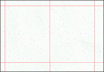
Grid layout. The boundaries of the MICs are marked with red lines. (filter)
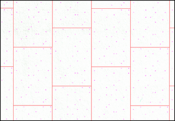
Checkerboard layout
The MIC is printed the same way as in the grid layout, but every other cell in the row of the
grid does not contain the MIC. Every other row is shifted by one horizontal position, creating
the checkerboard layout.

Checkerboard layout. The boundaries of the MICs are marked with red lines. (filter)
Diagonal layout
The MIC is printed in adjacent columns, with each subsequent column containing a vertical
shift by a predetermined constant. The shift for a particular pattern is always the same for
all MIC prints made according to it.
Diagonal layout. The boundaries of the MICs are marked with red lines. (filter)
Static segment
Most patterns contain a small static segment that is always located at the same position of
the MIC matrix. The static segment helps determine the pattern type and the boundaries of
individual MICs.

Example of static segments. The static segments are marked with green lines.
The boundaries of the MICs are marked with red lines. (filter)
This part of the MIC is always the same on all impressions of a given pattern and always
violates the dot printing rules defined by the pattern. This is done so that the same dot
sequence cannot appear in the part of the MIC that encodes information.
For example, if the pattern does not allow printing dots in adjacent cells, the static segment
can violate this rule and print dots in two cells that are immediately next to each other.
Information encoding
Each pattern type uses a unique method of encoding information into a two-dimensional matrix.
There is a pattern that simply encodes information binary into columns, but there is also a
pattern whose encoding method remains unknown. The encoding method is divided into:
-
direct, where information is directly encoded into the matrix and can be decoded into a
readable form with several steps (e.g. printer serial number)
-
indirect, which only provides us with an identification value for which there is likely
a matching table that the pattern creator probably has (e.g. printer manufacturer)